



Products
Ultrasonic (SAT) Inspection Systems
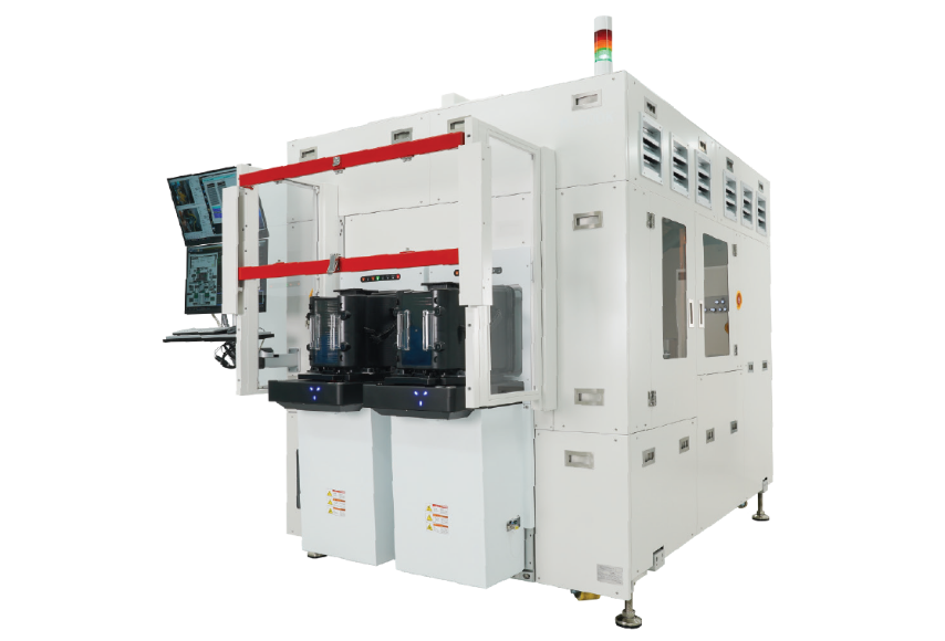
SFSAT-W (Wafer)
▪ Full Auto SAT for Wafer
▪ Multi Probe Head
▪ Transducer Frequency: 50~250MHz
▪ Scan Area: 300X300(mm)
▪ External Dimension: 1750X2200X2000(mm)
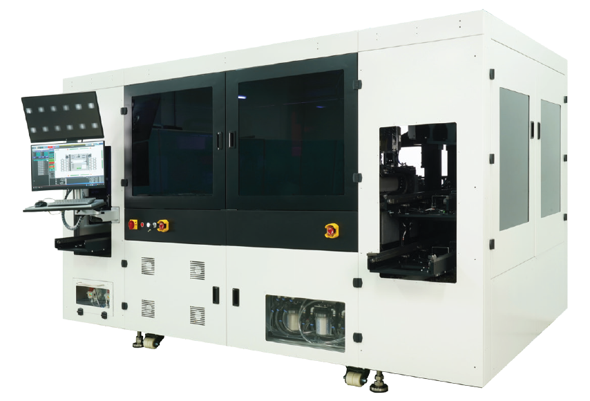
SFSAT-PAC (Advanced Package)
▪ Full Auto SAT for Package
▪ Multi Probe Head
▪ Transducer Frequency: 25~200MHz
▪ Scan Area: 300X200(mm)
▪ External Dimension: 3200X2000X2150(mm)
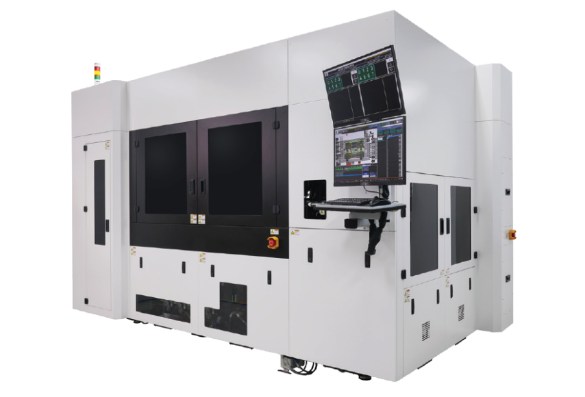
SFSAT-P (Power Module)
▪ Full Auto SAT for Power Module
▪ Multi Probe Head
▪ Transducer Frequency: 50~200MHz
▪ Scan Area: 300X200(mm)
▪ External Dimension: 3400X1800X2080(mm)
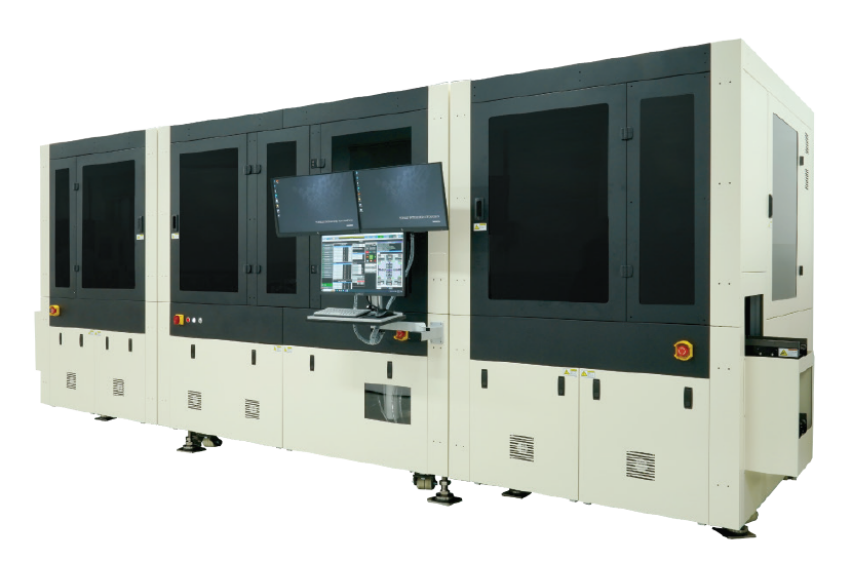
SFSAT-S (Substrate)
▪ Full Auto SAT for Substrate
▪ Multi Probe Head
▪ Transducer Frequency: 75MHz
▪ Scan Area: 200X200(mm)
▪ External Dimension: 5500X2000X2170(mm)
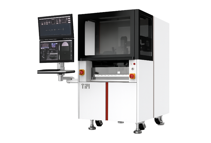
SFSAT-M (Manual)
▪ Full Auto Manual SAT
▪ Single or Multi Probe Head
▪ Transducer Frequency: 50~200MHz
▪ Scan Area: 300X200(mm)
▪ External Dimension: 840X1150X1960(mm)
Model differences at a glance
SFSAT models are divided by the form of the sample. Multi-probe parallel scanning (two or more inspection zones configurable), real-time warpage compensation of ±3 mm, a maximum scan speed of 1,200 mm/s, non-immersion coupling, deep-learning-based automatic judgment and SECS/GEM integration are common to all models.
| Model | Sample | When to choose it | Transducer | Scan area |
|---|---|---|---|---|
| SFSAT-W | Wafer | 100% in-line inspection of voids and particles at wafer-bonding interfaces and in stacked wafers | 50–250 MHz | 300 × 300 mm |
| SFSAT-PAC | Advanced package | Underfill voids, bump cracks and delamination in FC-BGA, 2.5D/3D and chiplet packages | 25–200 MHz | 300 × 200 mm |
| SFSAT-P | Power semiconductor module | Solder and sintered-joint voids between DCB/AMB substrate, chip and base plate | 50–200 MHz | 300 × 200 mm |
| SFSAT-S | Substrate | Internal cracks and delamination in ceramic and multilayer ceramic substrates | 75 MHz | 200 × 200 mm |
| SFSAT-M | General (manual loading) | Research, failure analysis and low-volume, high-mix samples that need no automatic loader; single or multi-probe head | 50–200 MHz | 300 × 200 mm |
Higher frequency gives finer resolution and shallower penetration. Throughput depends on scan pitch and on the number of probes and inspection zones, so it must be compared under the same conditions and is advised after evaluation of the sample. For the principle and terminology, see the SAT Technology Guide.
Related technical article
SAT (Scanning Acoustic Tomography) Technology GuidePrinciples of SAT, frequency selection, detectable defects, in-line versus laboratory systems, and a comparison with X-ray and IR inspection.
Also in this series: Why SAT·Why MIT SAT
Sample evaluation and technical consultation
Have a question? Just ask.
A one-line note about what you would like to inspect is enough. Our team will get back to you with a suitable model and evaluation options.
Contact us by e-mail